A Tower Top Amplifier (TTA) system improves base station receiver performance at a communications network site by placing the base station receiver system’s preselector and low-noise amplifiers close to the receive antenna(s), overcoming the increased system noise figure and receiver sensitivity degradation introduced in a communications system by the insertion loss of the coaxial feeder cables.
This coaxial feeder cable loss degradation increases over longer cable lengths and at higher frequencies, and TTAs are therefore particularly beneficial for UHF systems installed using very long coaxial cable feeders on large towers or buildings, or for any system operating in the higher (i.e. 7/8/900MHz) frequency bands.
Overview
The TA Series is a full-featured, high performance TTA system utilising exceptional preselector selectivity and redundant quadrature-coupled ultra low noise amplifiers (LNAs) to improve the base station receiver sensitivity performance of a network site. TTA system configurations are available for use with networks using base stations fitted with single receivers, dual receivers, or receiver diversity systems.
The TTA system is compatible with analogue and digital networks and comprises two components; the Tower Top Amplifier (TTA), and a Receiver Multicoupler/TTA Controller unit (RMC), and provides the following features:
- Exceptional frequency selectivity
- Redundant TTA quadrature Low Noise Amplifiers
- Extensive circuit monitoring and alarm management
- Test ports and test functionality supports testing and commissioning
- Convenient front panel controls
- User-friendly webserver Graphical User Interface (GUI)
- Auto Gain, Auto Mode, Gain Boost, Auto Bypass and Auto Recover functions
- SNMP, SMTP (Email) and Form-C relay contacts for fault reporting
- 12VDC, 24VDC, 48VDC or 90-264VAC versions available
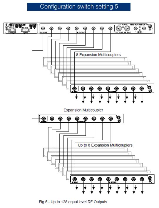
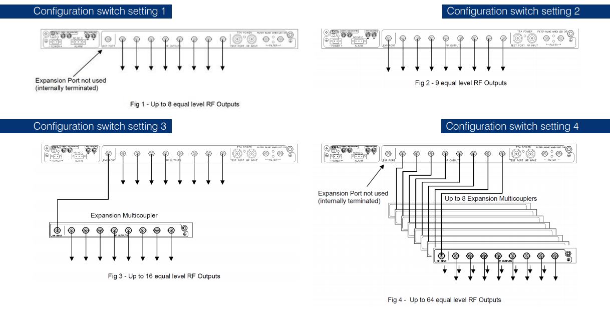
The Receiver Multicoupler unit features a comprehensive microprocessor-controlled status and fault monitoring capability that controls switching of the TTA’s redundant LNAs. Front and rear panel switches and indicators provide system configuration and fault status functions. A unique History capability displays measured performance parameters and alarm events to assist system performance analysis and fault-finding activities. The RMC itself supports 8 (or 9) RF outputs, and expansion up to 128 outputs is easily implemented using Receiver Multicoupler Expansion units connected to the RMC unit.
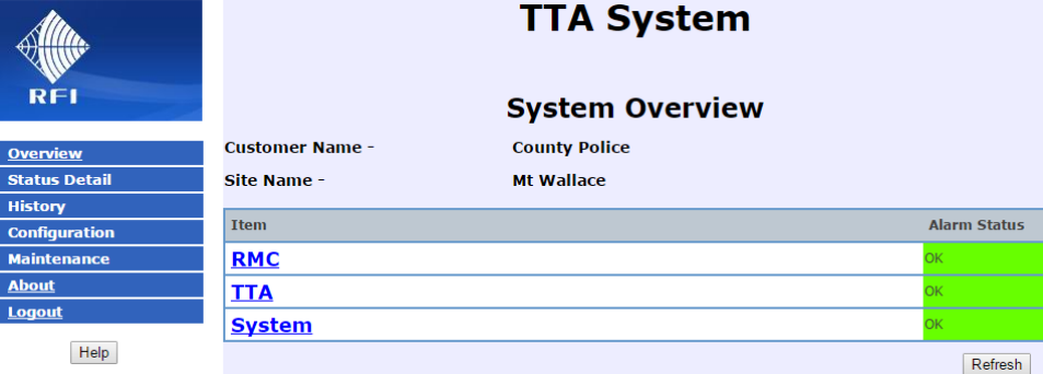
The TTA system also features Bypass, Terminated and Test Port functionality to support commissioning, fault-finding and maintenance activities. Additional features including Auto Gain, Auto Mode, Gain Boost, Auto Bypass and Auto Recover functionality, diagnostics monitoring and alarm reporting, and communications management are also available via the integral webserver GUI.
Enhanced Features - TTA
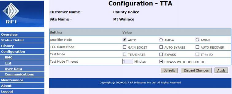
Amplifier Mode
The TTA redundant quadrature low noise amplifiers (LNAs) can be configured to automatically operate using either Amplifier Path A, Amplifier Path B or, when Auto Mode is selected, to continuously monitor both amplifier paths and automatically switch between them if a fault in either path is detected. Auto Mode ensures that the TTA provides the highest levels of fault tolerance and outage resiliency, and increases likely network availability.
TTA Alarm Mode
The Auto Bypass feature allows the TTA to bypass both LNAs in the unlikely event of a failure in both RF signal paths. When in this bypass mode, the TTA preselector is connected directly to the RMC, with the gain of the TTA LNAs no longer provided. This reduced-gain TTA state will allow the communications system to continue to operate, albeit at a reduced level of inbound or (‘talk-in’) coverage performance.
The Gain Boost feature enhances the Auto Bypass capability by allowing the Receiver Multicoupler to automatically apply its maximum available gain to the RF signal path when the TTA system has switched to the bypass mode. This additional RMC gain can assist in compensating for the reduced performance level of the TTA when in the bypass state.
A further level of management is provided by the Auto Recover feature. If a failure in both LNAs has occurred, and if Auto Recover is selected, the TTA will continuously monitor the fault state of both RF paths, checking if one (or both) LNAs’ fault condition clears. If a LNA returns to a serviceable state, the TTA will automatically revert out of its bypassed state – if Auto Bypass was enabled, resume it’s configured gain values – disabling Gain Boost if selected, and restoring the TTA system’s performance to its normal parameters.
Test Mode
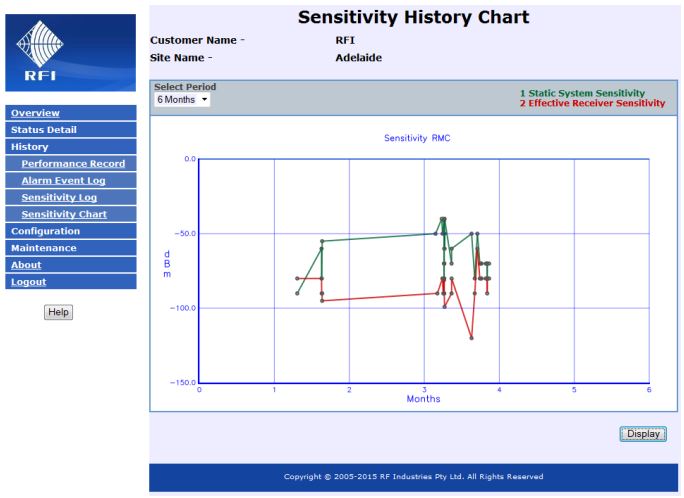
The Test Mode selections place the TTA in different configurations to facilitate to measurement of Static Site Sensitivity and Effective Site Sensitivity during commissioning, testing and maintenance activities. The Receiver Multicoupler’s front panel Test Port can also be switched to monitor the RF signals from the TTA directly. Test Mode settings are limited to only be applied for the duration of the Test Mode TimeOut period – ensuring a TTA system is not inadvertently left in a Test state.
History
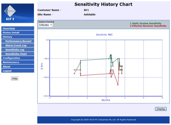
The Static Site Sensitivity and Effective Site Sensitivity measured values obtained using the Test Mode selections can be stored in the RMC with a time and date stamp. This Sensitivity Chart, a Sensitivity Log and an Alarm Event Log can be viewed (or downloaded) when desired – to analyze the TTA systems performance over time.
Enhanced Features - Receiver Multicoupler
Post Filter
An optional post-filter may be easily connected to the RMC – narrowing the system’s frequency passband and further enhancing the rejection of unwanted signals. Post filters are connected to the RMC and enabled in the webserver GUI. The GUI and a rear panel LED indicator displays the status of post-filter selection.
Settings Control
Configuration of the RMC can either be set via switches on its rear, or via the webserver GUI (LAN). LED indicators on the front panel display the Settings Control state. In the GUI, the yellow highlighted values are those being used by the system.
Hardware Configuration
The hardware configuration determines the output capacity and gain of the system (refer Output Capacity Configurations diagrams). Multiple configurations of output capacity are available for selection.
Input Gain Attenuator
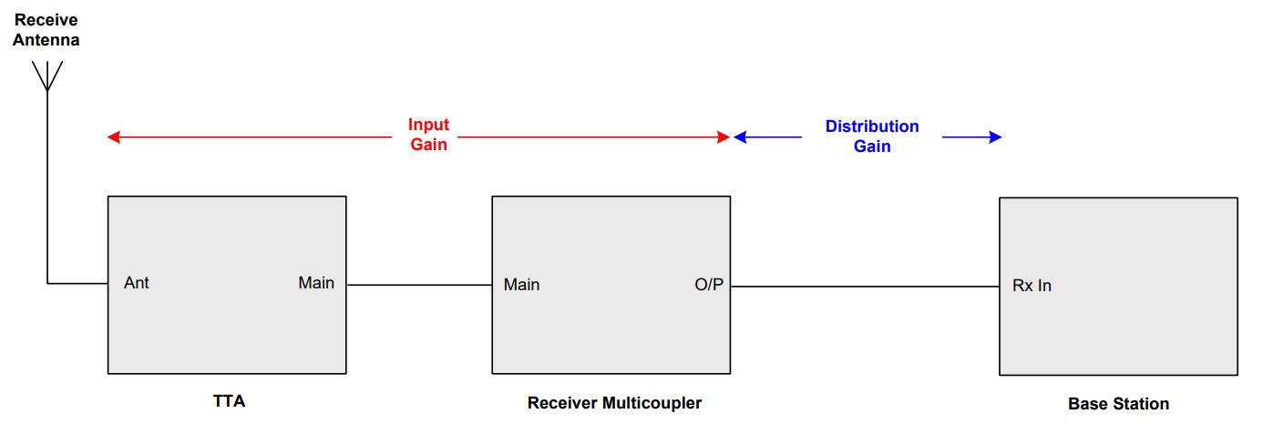
This setting configures the system’s Input Gain value. The Input Gain is the value measured between the Antenna port of the TTA, and an output port of the RMC. If the AUTO box is selected, the most appropriate Input Gain is calculated by using the values from the Auto Input and Distribution Attenuation field values.
Distribution Gain Attenuator
This setting configures the system’s Distribution Gain value. The Distribution Gain is the value measured between the output port of the RMC, and the receiver port of the network site’s base station.
This gain overcomes the insertion loss of the coaxial cable connecting the RMC to the base station. If the AUTO box is selected, the most appropriate Distribution Gain is calculated by using the values from the Auto Input and Distribution Attenuation field values.
Applications
The TA Series of Tower Top Amplifiers systems are ideally suited to a wide range of applications supporting wireless networks. These systems support the use of both analogue and digital protocols as used by FDMA and TDMA based networks.
TTA system configurations are available for use with networks using base stations fitted with single receivers, dual receivers, or receiver diversity systems. The user-friendly integral Graphical User Interface (GUI) displays the TTA, RMC and System alarm statuses, allows parameter configuration, and is compatible with computer and handheld device users. The SNMP, SMTP (Email) and Form-C dry relay contacts provide a broad range of alarm notification capabilities.
Single Receiver Networks
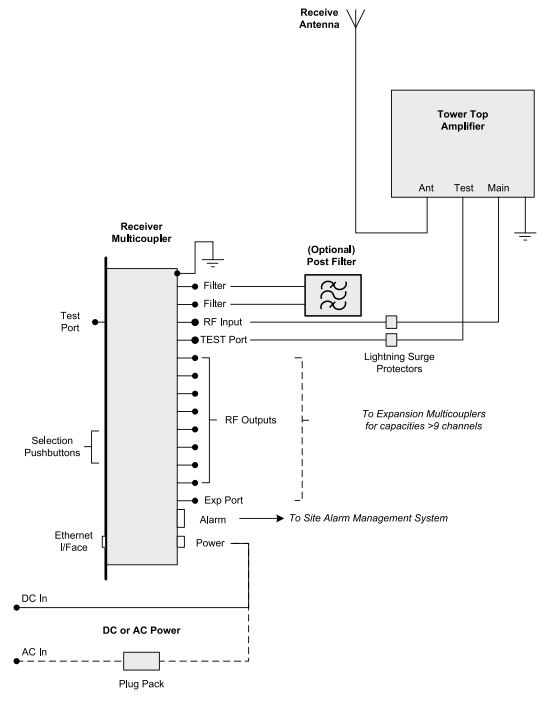
Many communications systems use repeater base stations fitted with a single receiver. To support network architecture, a configuration using a single TTA and RMC (and Expansion Multicouplers if required) may be deployed.
Diversity Receiver Networks
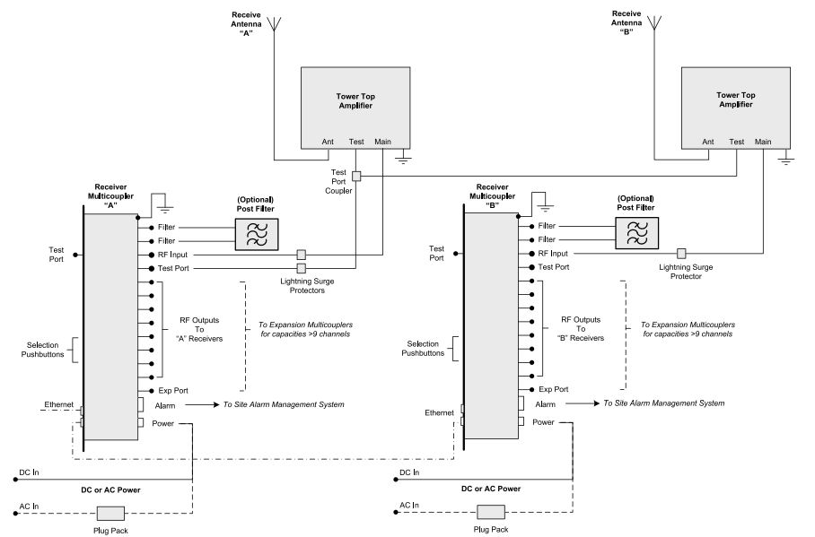
Systems using Diversity Receive architectures can be deployed using the Dual TTA Mounting Kit and two sets of TTA and RMC units. This configuration provides a fullyredundant, space-efficient Diversity Receive installation with minimal tower loading, and also provides a cost-effective and easily implemented migration path from single receiver to diversity receiver technologies (i.e. FDMA APCOP25 Phase 1 to TDMA APCOP25 Phase 2) where diversity receivers are desired. This migration path also supports the re-use of existing TTA and RMC units, and existing ‘Spares’ inventories. Site tower installations can be conveniently upgraded to use dual TTA without requiring additional equipment mounting locations, with the Dual TTA Mounting Kit using the same mounting brackets as the existing single TTA.
Dual Receiver Networks
Systems using Dual Receivers can be deployed using the same dual TTA/RMC architecture as is used for Diversity Receiver configurations. This full redundancy of the hardware in the Diversity Receiver and Dual Receiver configurations provide the highest levels of fault tolerance and network availability.
Using In-Line Post Filters
If a narrower frequency passband is desired, optional post-filters may be easily connected in-line with the RMC via connectors on its rear panel. A range of post filter models is available, enhancing the TTA system’s rejection of out-ofband (or other) unwanted signals.
Output Capacity Configurations
RFI Uploader Support
The TA Series products are supported by RFI’s Uploader software. Individual units, or a fleet of units, can have their firmware version checked, and be manually or automatically updated as desired. The Uploader software also checks communications connectivity to the units, allowing connectivity to be checked, tested and verified.
New Features, Upgrades, and Documentation
There is an active product development roadmap for the TA Series Tower Top Amplifier systems. New features are available in regular firmware releases.
Firmware updates can be easily uploaded (locally or remotely) to a TTA system. Firmware update files, SNMP MIB files, Service Bulletins and User Manuals are available from our website www.rfiamericas.com
Features & Benefits
- These products are compatible with both analogue and digital technologies. Exceptional TTA preselector selectivity enhances the rejection of unwanted signals and protects TTA, RMC and base station receiver circuitry from overload, performance degradation, and damage.
- The TTA’s two independent quadrature-style LNAs provide RF signal path redundancy – improving the communications network’s fault tolerance, outage resiliency, and increasing network reliability and availability.
- Post filters may be conveniently added to the RMC, narrowing the receiver passband and further enhancing the system’s rejection of unwanted frequencies.
- The TTA’s compact size reduces tower loading and congestion – particularly at crowded communications sites. An installation friendly mounting format is compatible with a wide range of building, pole and tower mounting scenarios.
- Diversity Receiver and Dual Receiver architectures are also supported. The total equipment redundancy in these systems provide the highest levels of fault tolerance, system reliability and network availability.
- The Dual TTA Mounting Kit provides a convenient and cost-effective technology migration path one that reduces deployment cost, installation space, and tower loading – while maximising the re-use of existing equipment and spares inventory investments.
- Extensive internal monitoring provides control of redundant LNAs switching, and alarm reporting for fault notification, response and rectification.
- Test Ports and Test functionality supports testing, commissioning and fault-finding activities. Bypass, Termination and Test Port modes assist commissioning and maintenance personnel. Static Site Sensitivity and Effective Site Sensitivity test results can be stored in the RMC for later viewing, analysis and downloading.
- Convenient and user-friendly RMC button controls, indicators and connector layout assists configuration and operation. A user-friendly webserver Graphical User Interface (GUI) may also be used for configuration, and also provides a suite of enhanced operational features; including Auto Gain, Auto Mode, Gain Boost, Auto Bypass and Auto Recover functions.
- Alarm reporting is available via SNMP, SMTP (Email) and Form-C relay contacts. Performance history charts and logs, and alarm log files are also available for viewing and downloading.
- Multiple power supply options are available to suit a wide range of deployment power systems including 12VDC, 24VDC, 48VDC or 90-264VAC.
